Fluke 434-II/BASIC - Basic Energy Analyzer
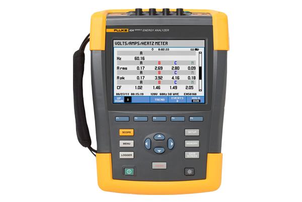

Analyze Power Quality Issues and Monetize Energy Waste
As energy saving equipment becomes more and more prevalent in facilities the need to discover where energy is being wasted is becoming more and more important. At the same time these pieces of energy saving equipment like motor drives and electronic lighting have the potential to disrupt the electrical system due to power quality problems. The Fluke 434 Series II Power Quality and Energy Analyzer can monetize the cost of energy waste due to poor power quality and is ideal for characterizing power quality, conducting load studies and capturing hard-to-find voltage events over a user-defined period of time. The Fluke 434 II Energy Analyzer is the ideal tool for advanced energy logging and energy monetization, identifying the most energy-wasteful areas of your facility.
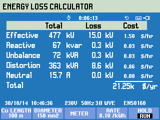
With its energy logging capabilities and the Energy Loss Calculator function, the 434 II measures the fiscal cost of energy wasted due to poor power quality issues in real dollars. Add basic power quality measurements to the package and you’ve got yourself one powerful troubleshooting tool.
The Fluke 434 II Energy Analyzer is the best general purpose power quality and energy analyzer. If you’re looking for advanced power quality and energy analysis capabilities, the Fluke 435 II is second to none.
Applications
- Energy Monetization – Calculate the fiscal cost of energy waste due to poor power quality.
- Energy Assessment – Quantify the before and after installation improvements in energy consumption to justify energy saving devices.
- Frontline Troubleshooting – Quickly diagnose problems on-screen to get your operation back online.
- Predictive Maintenance – Detect and prevent power quality issues before they cause downtime.
- Long-Term Analysis – Uncover hard-to-find or intermittent issues.
- Load Studies – Verify electrical system capacity before adding loads.
- Troubleshoot Real-Time: Analyze the trends using the cursors and zoom tools.
- Automatic Trending: Every measurement is always automatically recorded, without any set-up.
- Logger Function: Configure for any test condition with memory for up to 600 parameters at user defined intervals.
- Measure All Three Phases and Neutral: With included four flexible current probes with enhanced thin flex design to fit into the tightest places.
- Power Inverter Efficiency: Simultaneously measure AC output power and DC input power for power electronics systems using optional DC clamp.
- Energy Loss Calculator: Classic active and reactive power measurements, unbalance and harmonic power, are quantified to pinpoint the fiscal costs of energy losses.
- Highest Safety Rating in the Industry: 600 V CAT IV/1000 V CAT III rated for use at the service entrance.
- System-Monitor: Ten power quality parameters on one screen according to EN50160 power quality standard.
- View Graphs and Generate Reports: With included analysis software.
- Battery Life: Seven hours operating time per charge on Li-ion battery pack.
Powerful Troubleshooting Capabilities
The Fluke 430-II products were specifically designed with the needs maintenance engineers and technicians in mind; users who need to get to the solution of the power quality problem as quickly as possible so that they can minimize expensive downtime. The measurement process and display of data is optimized to get to the most important information as quickly as possible. Multiple parameters are measured simultaneously and displayed in formats that quickly describe the state of the power quality of the system. Data can be quickly accessed as simple digital values, trend graphs, waveforms, phasor diagrams or analyzed and organized into tabular format such as the event data where the magnitude, duration and time stamping enable rapid correlation to problems experienced.
AutoTrend - Quickly See the Trend
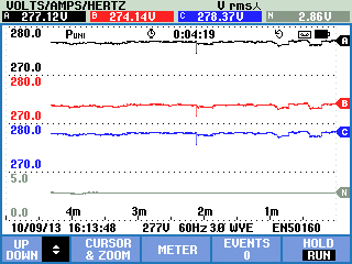 Unique AutoTrend gives you fast insight into changes over time. Every displayed reading is automatically and continuously recorded without having to set up threshold levels or having to manually start the process. You can quickly view trends in voltage, current, frequency, power, harmonics or flicker on all three phases plus neutral.
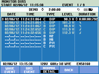
The System-Monitor Overview Screen
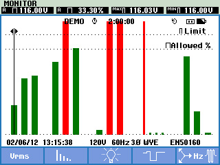 Instant insight into whether the voltage, harmonics, flicker, frequency and the number of dips and swells fall outside the set limits. A detailed list is given of all events falling outside the set limits.
Power Inverter Efficiency
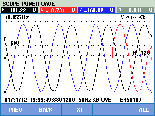 Power inverters take DC current and transform it into AC current, or vice versa. Solar generation systems usually include an inverter that takes the DC energy from the solar cells and converts it to useful AC power. Inverters can lose performance over time and need to be checked. By comparing the input power with the output power you can determine the system efficiency. The 430 series II can measure the efficiency of such inverters by simultaneously measuring the DC and AC power of a system to determine how much power is lost in the conversion process.
Unified Power Measurement
 Previously, only experts could calculate how much energy was wasted due to power quality issues; utilities could calculate the cost, but the required measurement process was beyond the reach of average electricians. With this patented Unified Power function you can use one handheld tool to determine how much power is being wasted, and calculate exactly what the extra consumption costs.
Fluke’s patented Unified Power Measurement System provides the most comprehensive view of power available, measuring:
- Parameters of Classical Power (Steinmetz 1897) and IEEE 1459-2000
- Detailed Loss Analysis
- Unbalance Analysis
These UPM calculations are used to quantify the fiscal cost of energy loss caused by power quality issues. The calculations are computed, along with other facility-specific information by an Energy Loss Calculator that ultimately determines how much money a facility loses due to wasted energy
SystemMonitor - Check Performance Against EN50160 with Ease
 The unique System-Monitor gives you an overview of power system performance (there is no button or single function) and checks the compliance of incoming power to EN50160 limits or to your own custom specifications. The overview is shown on a single screen, with color-coded bars clearly indicating which parameters fall outside the limits.
|
Track harmonics up to the 50th, and measure and record THD in accordance with IEC61000-4-7 requirements |
Logging function allows you to customize measurement selections and provides instantaneous analysis of user-selectable parameters. |
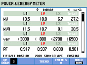
Measure and record power (W), VA and VARs, PF and energy consumption. |
| Product Specifications | ||||
| Volt | Model | Measurement Range | Resolution | Accuracy |
| Vrms (AC + DC) | 1 V to 1000 V phase to neutral | 0.1 V | ±0.5% of nominal voltage4 | |
| Vpk | 1 Vpk to 1400 Vpk | 1 V | 5% of nominal voltage | |
| Voltage Crest Factor (CF) | 1.0 > 2.8 | 0.01 | ±5% | |
| Vrms½ | 1 V to 1000 V phase to neutral | 0.1 V | ±1% of nominal voltage | |
| Vfund | 1 V to 1000 V phase to neutral | 0.1 V | ±0.5% of nominal voltage | |
| Amps (accuracy excluding clamp accuracy) | ||||
| Amps (AC + DC) | i430-Flex 1x | 5 A to 6000 A | 1 A | ±0.5% ±5 counts |
| i430-Flex 10x | 0.5 A to 600 A | 0.1 A | ±0.5% ±5 counts | |
| 1 mV/A 1x | 5 A to 2000 A | 1 A | ±0.5% ±5 counts | |
| 1 mV/A 10x | 0.5 A A to 200 A (AC only) | 0.1 A | ±0.5% ±5 counts | |
| Apk | i430-Flex | 8400 Apk | 1 Arms | ±5% |
| 1 mV/A | 5500 Apk | 1 Arms | ±5% | |
| A Crest Factor (CF) | 1 to 10 | 0.01 | ±5% | |
| Amps½ | i430-Flex 1x | 5 A to 6000 A | 1 A | ±1% ±10 counts |
| i430-Flex 10x | 0.5 A to 600 A | 0.1 A | ±1% ±10 counts | |
| 1 mV/A 1x | 5 A to 2000 A | 1A | ±1% ±10 counts | |
| 1 mV/A 10x | 0.5 A A to 200 A (AC only) | 0.1 A | ±1% ±10 counts | |
| Afund | i430-Flex 1x | 5 A to 6000 A | 1 A | ±0.5% ±5 counts |
| i430-Flex 10x | 0.5 A to 600 A | 0.1 A | ±0.5% ±5 counts | |
| 1 mV/A 1x | 5 A to 2000 A | 1 A | ±0.5% ±5 counts | |
| 1 mV/A 10x | 0.5 A A to 200 A (AC only) | 0.1 A | ±0.5% ±5 counts | |
| Hz | ||||
| Fluke 434 @ 50 Hz nominal | 42.50 Hz to 57.50 Hz | 0.01 Hz | ±0.01 Hz | |
| Fluke 434 @ 60 Hz nominal | 51.00 Hz to 69.00 Hz | 0.01 Hz | ±0.01 Hz | |
| Power | ||||
| Watts (VA, var) | i430-Flex | max 6000 MW | 0.1 W to 1 MW | ±1% ±10 counts |
| 1 mV/A | max 2000 MW | 0.1 W to 1 MW | ±1% ±10 counts | |
| Power Factor (Cos j/DPF) | 0 to 1 | 0.001 | ±0.1% @ nominal load conditions | |
| Energy | ||||
| kWh (kVAh, kvarh) | i430-Flex 10x | Depends on clamp scaling and V nominal | ±1% ±10 counts | |
| Energy Loss | i430-Flex 10x | Depends on clamp scaling and V nominal | ±1% ±10 counts Excluding line resistance accuracy | |
| Harmonics | ||||
| Harmonic Order (n) | DC, 1 to 50 Grouping: Harmonic groups according to IEC 61000-4-7 | |||
| Inter-Harmonic Order (n) | OFF, 1 to 50 Grouping: Harmonic and Interharmonic subgroups according to IEC 61000-4-7 | |||
| Volts % | f | 0.0% to 100% | 0.1% | ±0.1% ± n x 0.1% |
| r | 0.0% to 100% | 0.1% | ±0.1% ± n x 0.4% | |
| Absolute | 0.0 to 1000 V | 0.1 V | ±5%1 | |
| THD | 0.0% to 100% | 0.1% | ±2.5% | |
| Amps % | f | 0.0% to 100% | 0.1% | ±0.1% ± n x 0.1% |
| r | 0.0% to 100% | 0.1% | ±0.1% ± n x 0.4% | |
| Absolute | 0.0 to 600 A | 0.1 A | ±5% ±5 counts | |
| THD | 0.0% to 100% | 0.1% | ±2.5% | |
| Watts % | f or r | 0.0% to 100% | 0.1% | ± n x 2% |
| Absolute | Depends on clamp scaling and V nominal | — | ±5% ± n x 2% ±10 counts | |
| THD | 0.0% to 100% | 0.1% | ±5% | |
| Phase Angle | -360° to +0° | 1° | ± n x 1° | |
| Flicker | ||||
| Plt, Pst, Pst (1 min) Pinst | 0.00 to 20.00 | 0.01 | ±5% | |
| Unbalance | ||||
| Volts % | 0.0% to 20.0% | 0.1% | ±0.1% | |
| Amps % | 0.0% to 20.0% | 0.1% | ±1% | |
| Mains Signaling | ||||
| Threshold Levels | Threshold, limits and signaling duration is programable for two signaling frequencies | — | — | |
| Signaling Frequency | 60 Hz to 3000 Hz | 0.1 Hz | ||
| Relative V % | 0% to 100% | 0.10% | ±0.4% | |
| Absolute V3 s (3 second avg.) | 0.0 V to 1000 V | 0.1 V | ±5% of nominal voltage | |
| General Specifications | ||||
| Case | Design Rugged, shock proof with integrated protective holster Drip and dust proof IP51 according to IEC60529 when used in tilt stand position Shock and vibration Shock 30 g, vibration: 3 g sinusoid, random 0.03 g 2 /Hz according to MIL-PRF-28800F Class 2 | |||
| Display | Brightness: 200 cd/m 2 typ. using power adapter, 90 cd/m 2 typical using battery power Size: 127 x 88 mm (153 mm/6.0 in diagonal) LCD Resolution: 320 x 240 pixels Contrast and brightness: user-adjustable, temperature compensated | |||
| Memory | 8GB SD card (SDHC compliant, FAT32 formatted) standard, upto 32GB optionally Screen save and multiple data memories for storing data including recordings (dependent on memory size) | |||
| Real-Time Clock | Time and date stamp for Trend mode, Transient display, System Monitor and event capture | |||
| Environmental | ||||
| Operating Temperature | 0°C ~ +40°C; +40°C ~ +50°C excl. battery | |||
| Storage Temperature | -20°C ~ +60°C | |||
| Humidity | +10°C ~ +30°C: 95% RH non-condensing +30°C ~ +40°C: 75% RH non-condensing +40°C ~ +50°C: 45% RH non-condensing |
|||
| Maximum Operating Altitude | Up to 2,000 m (6666 ft) for CAT IV 600 V, CAT III 1000 V Up to 3,000 m (10,000 ft) for CAT III 600 V, CAT II 1000 V Maximum storage altitude 12 km (40,000 ft) |
|||
| Electro-Magnetic-Compatibility (EMC) | EN 61326 (2005-12) for emission and immunity | |||
| Interfaces | Mini-USB-B, Isolated USB port for PC connectivity SD card slot accessible behind instrument battery | |||
| Warranty | Three years (parts and labor) on main instrument, one year on accessories | |||
| 1. ±5% if ≥ 1% of nominal voltage ±0.05% of nominal voltage if < 1% of nominal voltage 2. 50Hz/60Hz nominal frequency according to IEC 61000-4-30 3. 400Hz measurements are not supported for Flicker, Mains Signaling and Monitor Mode 4. For nominal voltage 50 V to 500 V |
||||
Do you have a Basic Energy Analyzer that needs to be calibrated?
We offer standard traceable calibration and ISO 17025 accredited calibration services.
Get your Basic Energy Analyzer calibrated today! Click Here!
There are currently no reviews for this product.